


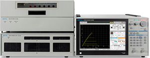
Semiconductor Curve Tracer CS-8000 Series
With a variety of unit combinations, it supports next-generation semiconductor measurement, and is ideal for characterization in all processes.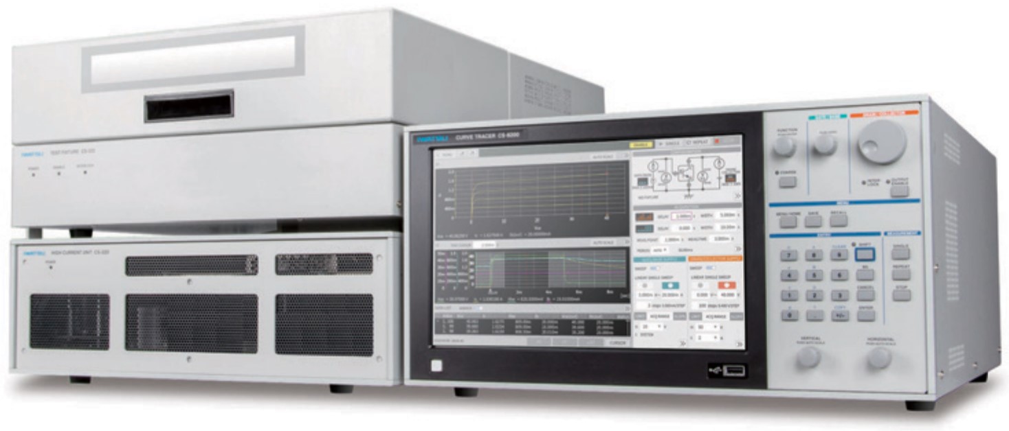
- High power test at up to 5kV, up to 2,000A
- Accurate microcurrent measurement (resolution 250fA)
- Large 12.1-inch touchscreen
- Various GATE signal output functions
- Extensive temperature characteristic measurement options
- High-power on-wafer tests with prober
General Specifications
Gate voltage:±40 V Voltage range:0.2 ~ 5 kV Maximum measurement current:2 kA Current measurement resolution:250 fA
Advantages during actual measurements
- Compatible with SiC and GaN devices
- Supports wafers and low-power devices
- High-power devices are also supported
- Supports microcurrent measurement
Easy to use UI
Equipped with a 12.1-inch TFT-LCD (1280x800) high-definition and large-screen display, it can be operated with a touch screen, the function keys on the front panel, and independent knobs for each function.
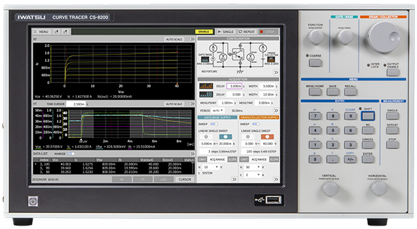
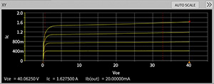
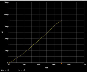
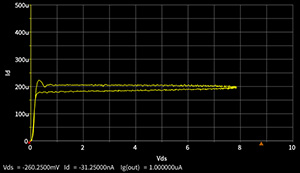
① X-Y display area
Any voltage/current parameters can be set on the X-axis and Y-axis respectively, and various semiconductor characteristic curves such as Vds-Id characteristics, threshold voltage, and Vds-Vgs saturation characteristics can be displayed. In addition, you can set multiple parameters on the Y-axis. Scale can be switched between Log and Linear.
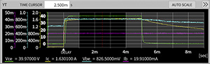
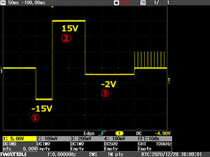
② Y-T display area
The measurement applied waveform is displayed on the time axis like an oscilloscope. Since waveform abnormalities such as pulse width, measurement point, and oscillation can be checked in real time, it is easy to verify whether accurate measurements have been made. Since all applied waveform data can be saved at the same time as the data displayed in the X-Y display, the measurement results can be revalidated.
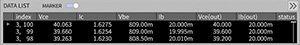
③ Measured data display area
Detailed measurement results, measurement conditions, and status are displayed in text format.
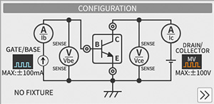
④ Configuration setting area
Sets the measurement configuration of a device. Supports the selection of voltage/current units, wiring changes, etc. in a graphical display
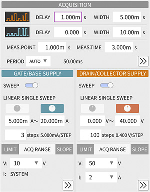
⑤ Parameter setting area
This area is used to set measurement parameters and measurement limits, and to switch between manual and automatic measurements.
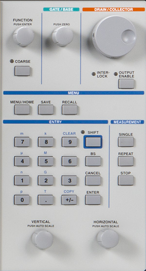
⑥ Control panel
The front panel has buttons and rotary knobs for easy manual measurements. On the numeric keypad located in the center, you can enter numeric values for parameters. DRAIN/COLLECTOR, GATE/BASE, Manual measurement can be easily performed with vertical-axis and horizontal-axis rotary knobs.
Output sources tailored to the application
You can arbitrarily select the voltage and current units required for measurement according to the application.
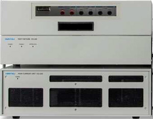
The picture on the right shows,
Upper section:Test fixture
Lower section:High current unit
HV unit
This is a 2kV, 5kV high voltage unit. The DC/pulse wave can be selected. You can select constant voltage and constant current drive measurement.
| Main unit | CS-8200 | CS-8500 |
|---|---|---|
| Maximum voltage (Maximum current) |
2 kV (20 mA) |
5 kV (8 mA) |
| Waveform | DC, Pulse | |
| Polarity | Positive/negative | |
| Measurement current resolution | 250 fA | |
MV unit (common to all main units)
This is a medium voltage unit of 200V. You can select constant voltage and constant current drive measurement. In addition to DC and pulse, SIN, half-wave, and full-wave waveforms can be selected.
| Maximum voltage (Maximum current) |
200 V(2 A) |
|---|---|
| Waveform | DC(200 mA), Pulse (2A), SIN, Half-wave, full-wave |
| Polarity | Positive/negative/both polarities |
| Measurement current resolution | 250 fA |
GATE unit (common to all main units)
This is a 40V unit. You can select constant voltage and constant current drive measurement. In addition to DC and pulse, SIN can be selected.
| Maximum voltage (maximum current) | 40 V(1 A) |
|---|---|
| Waveform | DC, pulse, SIN |
| Polarity | Positive/negative/both polarities |
| Measurement current resolution | 250 fA |
HC unit
The high-current mode supports high-current measurements up to 2,000A. Pulse width, measurement period, and measurement range can be varied
| HC Unit |
CS-205 | CS-210 | CS-220 |
|---|---|---|---|
| Maximum current (Voltage) |
500 A (50 V) |
1 kA (50 V) |
2 kA (50 V) |
| Waveform | Pulse | ||
| Pulse width | 10µs~1ms | 10µs~500µs | |
| Polarity | Positive/negative | ||
Minimum current resolution250 fA
By adopting triaxial and optimizing the measurement system, leakage and noise in the equipment are reduced, so stable measurement of micro-currents is possible.
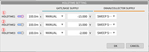
Various GATE signal outputs
The GATE signal can be sequenced and applied.
Hold time variable range
0.000[s] ~ 5.000[s]
Preliminary signal voltage range
Gate -40[V] ~ +40[V]
Hysteresis measurement
The CS-8000 has useful functions for measuring wideband gap semiconductors such as SiC and GaN with hysteresis.
The double sweep function displays the UP sweep and DOWN sweep at the same time, so hysteresis can be observed.
Safety mechanism
In addition to the interlock function, it is equipped with an output limit function.
You can set the voltage, current, and power limits to prevent damage to the DUT.
In addition, the overcurrent protection function of the hardware shuts off the current when it flows 1.4 times the measurement range.

Combination configuration
The HC unit and fixture can be selected according to the voltage and current of the measurement target.
Main unit:CS-8200
HC unit:CS-220
Test fixture:CS-322 HV/HC
Accessories
HV standard cable set CS-021
HC standard cable set CS-022
CS-8000 Series Main Specifications
| Main unit model name | CS-8020 | CS-8200 | CS-8500 | |
|---|---|---|---|---|
| HV unit | ||||
| Maximum peak voltage (maximum current) | - | 2 kV(20 mA) | 5 kV(8 mA) | |
| Measurement voltage range (full scale) | - | 2 kV ~ 50 V | 5 kV ~ 50 V | |
| Measurement current range | - | 20 mA ~ 50 µA | 20 mA ~ 50 µA | |
| Minimum measurement current resolution | - | 250 fA | 250 fA | |
| Waveform | - | DC pulse | DC pulse | |
| MV unit | ||||
| Maximum peak voltage (maximum current) | 200 V(1 A) | |||
| Measurement voltage range (full scale) | 200 V ~ 200 mV | |||
| Measurement current range | 2 A ~ 5 nA | |||
| Minimum measurement current resolution | 250 fA | |||
| Waveform | DC(200 mA), Pulse (2A), SIN, half wave, full wave | |||
| GATE unit | ||||
| Maximum peak voltage (maximum current) | 40 V(1 A) | |||
| Measurement voltage range (full scale) | 50 V ~ 1 V | |||
| Measurement current range | 1 A ~ 5 nA | |||
| Minimum measurement current resolution | 250 fA | |||
| Waveform | DC pulseSIN (50 Hz) | |||
| Standard Accessories | Power cable, control interface terminator, instruction manual (booklet + CD) | |||
| HC unit model name | CS-205 | CS-210 | CS-220 |
|---|---|---|---|
| Maximum peak current (maximum voltage) | 500 A(50 V) | 1,000 A(50 V) | 2,000 A(50 V) |
| Measurement voltage range (full scale) | 50 V ~ 200 mV | 50 V ~ 200 mV | 50 V ~ 200 mV |
| Measurement current range | 500 A ~ 5 A | 1,000 A ~ 5 A | 2,000 A ~ 5 A |
| Waveform | Pulse (Width 10µs to 1ms) |
Pulse (Width 10µs to 500µs) |
Pulse (Width 10µs to 500µs) |
| Standard Accessories | Power cable, HC-FIXTURE connection unit, instruction manual | ||
* Separate sense cables are required when using the HC unit.
| Test fixture model name | CS-320MV (coming soon) | CS-322HV/HC |
|---|---|---|
| Standard Accessories | Power cable, standard lead set (CS-005 set of 7), instruction manual | |
| - | HV/HC cable (2 pcs) | |
* If you wish to connect the test fixture, you will need a separate cable.
Cable (used for connecting between the main unit and the test fixture or HC unit.)
| Model | Product name |
|---|---|
| CS-025 | HV cable (L = 1.0m) |
| CS-026 | Triaxial cable (L = 1.0m) |
| CS-027 | Control interface cable (L = 1.0m) |
| CS-028 | Interlock/sense cable (L = 1.0m) |
Cable set (A set of necessary cables.)
| Cable set name | Contents |
|---|---|
CS-020 MV standard cable set (Recommended set for CS-320) |
CS-026 (Triaxial cable L=1.0m) x 7 pcs |
| CS-027 (Control interface cable L=1.0m) x 1 pc | |
| CS-028 (Interlock/sense cable L=1.0m) x 1 pc | |
CS-021 HV standard cable set (Recommended set for CS-322) |
CS-025 (HV cable L=1.0m) x 2 pcs |
| CS-026 (Triaxial cable L=1.0m) x 7 pcs | |
| CS-027 (Control interface cable L=1.0m) x 1 pc | |
| CS-028 (Interlock/sense cable L=1.0m) x 1 pc | |
CS-022 HC standard cable set (Recommended set for HC unit) |
CS-027 (Control interface cable L=1.0m) x 1 pc |
| CS-028 (Interlock/sense cable L=1.0m) x 1 pc |
