


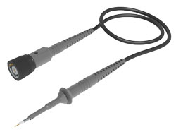
PML 711/721 High Impedance Probe
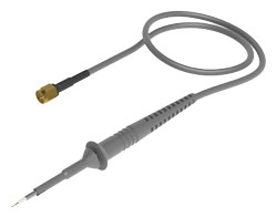
PML 50Ω type probe
■ 2.5 mm probe tip
■ Can be connected between 0.5mm and 1.27mm pitch pins
■ Can be exchanged for springs, tips, etc.
Accessories example
<Attention>Accessories may change due to changes in specifications.
- Probe main unit
- Instruction manual
- Spring tip 0.5mm (probe tip)
- CuBe probe tip 0.5mm (probe tip)
- Color ring 4 colors 3 pcs each
- Ground lead 11cm
- Ground blade 2.5
- Copper foil pad
- Insulator cap 2.5
- Protection cap 2.5
- IC cap 0.5-1.27 mm pitch
- Spring hook 2.5
- Ground spring 2.5
- PCB adapter kit 2.5
- 2-leg positioner
- Adjustment tool
(Not attached to the 50Ω type probe)
The compact design of the PML probe series with only 2.5mm housing diameter at the probe tip is ideal formeasurements on the smallest components and hard-to-reach measuring points, as it allows a far betterview of the component under test than conventional 5mm probe housing designs. The actual probe tip isonly 0.5mm thick, gold plated and spring loaded.
Individual contacting with high signal fidelity in different applications is ensured with the replaceable springtip and a variety of contacting accessories. Especially for RF measurements at the IC a shortest possibleground connection is necessary. BNC and PCB solder-in solutions are available. Conventional adaptationscause additional inductance and resonance into the measurement circuit due to long leads and thus distortthe measurement signal. This is where the innovative IC contacting system of the PML series, consisting of 5different IC caps for pin spacing from 0.5mm to 1.27mm, the innovative ground blade and the copper padfor gluing onto the IC, offers the ideal solution for short-circuit-proof, reproducible and accuratemeasurements.
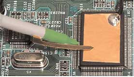
Probing to IC pins
using the IC cap and the ground blade
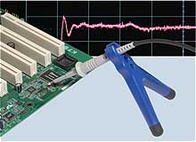
2-leg positioner (893-250-001)
Characteristic graph
PML 711 derating characteristics
PML 711 input impedance characteristics
Accessories
Probe calibration
We recommend that you use the probe after calibration.
The passive probe has an adjustment trimmer to match the oscilloscope.
Without this adjustment, it may appear that the waveforms at the rising and falling edges are rounded, overshooting, or undershooting. With such waveforms, the signal amplitude of narrow pulse widths cannot be accurately measured, so it is necessary to make adjustments.
If you decide to use the oscilloscope channel and the channel using the probe, you can use it without recalibrating from the next measurement.
Example of passive probe adjustment
Relationship between probe adjustment and waveform
(1st stage) Normal waveform after adjustment
(2nd stage) Overcompensated waveform
(3rd stage) Undercompensated waveform
Specifications
| Model name | Attenuation | Input RC | Frequency band (MHz) | Compatible input capacity [pF] | Measurement equipment side input impedance [Ω] | Maximum input voltage | Cable length [m] | |
|---|---|---|---|---|---|---|---|---|
| R[Ω] | C[pF] | |||||||
| PML 701 PML 701-RO |
1:1 | - | 39 (single probe) |
38 | 10~25 | 1M | 30Vrms, 60V DC |
1.3 |
| PML 711A PML 711A-RO |
10:1 | 10M | 9.5 | 500 | 10~25 | 1M | 300V (CATII) | 1.3 |
| PML 712 PML 712-RO |
10:1 | 10M | 11.5 | 350 | 10~25 | 1M | 300V (CATII) | 2 |
| PML 713 PML 713-RO |
10:1 | 10M | 14.5 | 250 | 10~25 | 1M | 300V (CATII) | 3 |
| PML 721 PML 721RO |
20:1 | 20M | 5.6 | 500 | 10~25 | 1M | 300V (CATII) | 1.2 |
| PML 751 PML 751-RO |
10:1 | 500 | 2 | 1,500 | 10~25 | 50 | 12V (DC+ACpeak) | 1.3 |
| PML 791 PML 791-RO |
100:1 | 5k | 2.6 | 1,500 | 10~25 | 50 | 30V (DC+ACpeak) | 1.3 |
* “-RO” in the model name corresponds to ReadOut.
* The connector on the measurement equipment connection side of all probes is BNC type.
* The PML751 and 791 can be changed to SMA connectors by custom order.
* The cable length can be changed by custom order.
