


1ch High Bandwidth Differential Amplifier IE-1165 Discontinued
Application
This is a differential amplifier (voltage probes are required separately) used in scenes where you want to observe switching waveforms (measurements such as IGBT Vce) of high voltage switching devices (IGBTs, FETs, GTOs, etc.); observe motor drive circuit gate signals, PWM waveforms; make noise-resistant measurements in noisy environments such as production lines; or make differential measurements in combination with high voltage probes.Overview
It has a differential input of 1CH and outputs the input signal at 10:1. You can obtain an output signal of 1,000:1 using a 100:1 probe. (Measurement up to 2kV is possible) The output is used by connecting to an oscilloscope (50Ω termination) with a coaxial cable. It has a wide bandwidth of 200MHz, so it can also be used to observe switching noise.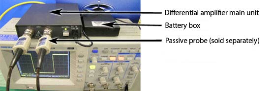
Figure 1:Example connection of a differential amplifier and a 10:1 probe attached to an oscilloscope in battery operation
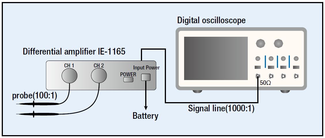
Figure 2:PHV1000 100:1 probe connection measurement system
General Specifications
| Order number | IE-1165 | |
|---|---|---|
| Input | Input | 1ch |
| Sensitivity | Range 10:1 Accuracy ±2% |
|
| Frequency characteristics | DC~200MHz -3dB | |
| Maximum allowable input voltage | ±250V MAX. | |
| Output | Output | 1ch output |
| Output sensitivity | 10:1 (50Ω) of input | |
| Output potential | ±2V MAX.(50Ω) | |
| Output resistance | 50Ω ±2V% | |
| Power supply part | Power supply range | DC +4.5V~+9.0V |
| Current consumption | Approx. 300mA (at 5V input) | |
| Mass and size | Weight | Approx. 0.25kg |
| Size | Approx. 110W × Approx. 28H × Approx. 115D mm * Accessories and protruding parts are not included. |
|
| Environmental conditions | Performance warranty temperature | 23°C ±5°C |
| Operating range | Temperature 10℃ to 35℃, humidity 80% RH (10℃ to 35℃) or less | |
| Storage range | Temperature -20°C to 60°C, humidity 80% RH (+35°C) or less | |
| Preheating time | The performance standard of this device is a guaranteed value after more than 30 minutes of power-on. | |
Examples of combinations with passive probes (voltage probes)
| Order number | Specifications |
|---|---|
| SS-0122 | 100MHz 1/10:1 switching probe (differential amplifier output 10:1/100:1) DC+Acpeak 600V |
| PHV 1000 | 400MHz 100:1 CAT 1 1000V ACrms or DC 4000V No readout pin |
| PHV 661-L | 380MHz 100:1 (differential amplifier output/1000:1) ACrms 2.8kV, VDC incl .pkAC 4.0kV, Impulse Peak 6kV No readout pin |
1-channel wideband differential amplifier that can also support high-voltage inputs
Differential amplifiers can be used for all kinds of measurements, such as high-voltage measurements and small-signal measurements at production sites.Why do we have to do differential measurements?
(1) Measuring in noisy environments
(2) Measure the measurement point where the reference potential is not at the GND level (0 potential)
(1) Measuring in noisy environments
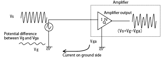
Figure 3:Single-ended input format
Figure 3 shows a simple circuit for a single-ended CH input. When a potential difference occurs between the ground of the amplifier input and the ground of the signal source, the noise (the potential difference between Vg and Vga) is superimposed and the waveform becomes distorted. Noise is superimposed on the signal even if it enters from the outside.
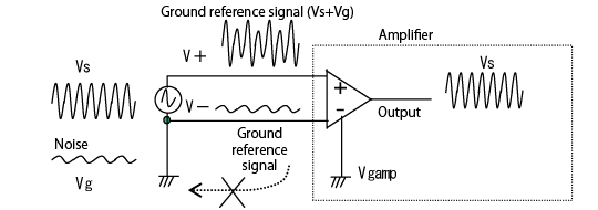
Figure 4:Differential input format
Therefore, we use a differential input format. The waveform of the signal source you want to measure can be measured with good resistance against noise by canceling the noise source and crosstalk noise generated on the ground of the signal generator even if the noise is superimposed.
An actual measurement example is shown in Figure 5 Single-ended input measurement and Figure 6 Differential measurement by combination of differential amplifier and voltage probe.
The effects of ground loop interference and crosstalk noise were observed. The cause was noise generated from the motor that was attached near the measurement point.
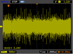
Figure 5:Single-ended input measurement
The effect of noise was reduced, and the differential measurement was highly effective.
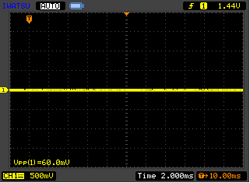
Figure 6:Differential measurement bycombination of differentialamplifier and voltage probe
(2) Measure the measurement point where the reference potential is not at the GND level (0 potential)
You can measure the signal level where the reference is not ground. The switching waveform on the high side of the 2-level motor drive circuit using a power device such as an IGBT shown in the figure can also be measured. High voltage measurement can be performed by combining PMK voltage probes handled by IWATSU.
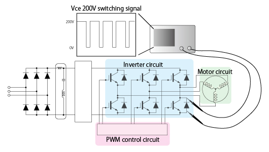
Figure 7:Example of level motor drive circuit
The example in Figure 7 shows the potential when measuring between the base of the small signal amplitude and the emitter where the high voltage appears. We recommend that you measure safely using a differential amplifier and a voltage probe when measuring with a non-ground voltage as the reference.
Floating measurements, where the ground side of the measuring device at the measurement point where a high voltage is applied is floating, are dangerous.
Use the isolation system DM-8000H to measure the Vge on the high side of the inverter, which is superimposed with large common mode noise, such as the Highside Vce measurement of the inverter.
