


Universal Counter SC-7205A Performance
Frequency A(FREQ-A, FREQ-B)
■ Measurement range and resolution |
|||
|---|---|---|---|
| Reference time (reference frequency) | 100ns(10MHz) | ||
| range | Coupling DC | 0.6mHz~230MHz | |
| Coupling AC | 10Hz~230MHz | ||
| Resolution and count method | Measured signal | Less than 10MHz | 10MHz or more |
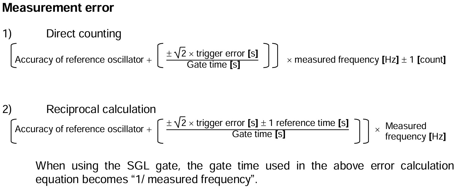
| Count method | Reciprocal count | Direct count | |
| 1ms gate | 4-digit | 1kHz | |
| 10ms gate | 5-digit | 100Hz | |
| 0.1s gate | 6-digit | 10Hz | |
| 1s gate | 7-digit | 1Hz | |
| 10s gate | 8-digit | 0.1Hz | |
| EXT-B gate * | Reciprocal count method. The maximum number of digits is determined by the EXT gate time. | ||
| SGL gate | Reciprocal count method. The number of digits is determined by the measured signal. | ||
* EXT-B cannot be used when using FREQ-B input.
• The reference oscillator accuracy is the temperature characteristic of the reference oscillator.
Frequency LINE(FREQ-LINE)
■ Measurement range and resolution |
|||
|---|---|---|---|
| Reference time | 100ns | ||
| range | 45Hz~440Hz | ||
| Resolution | 0.1s gate | 6-digit | |
| 1s gate | 7-digit | ||
| 10s gate | 8-digit | ||
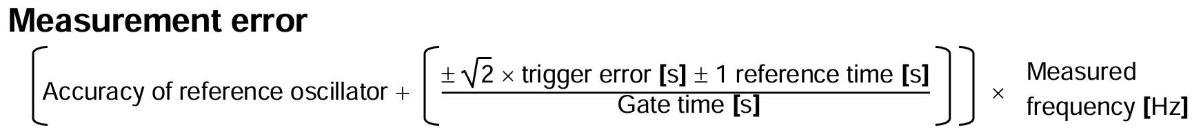
• The reference oscillator accuracy is the temperature characteristic of the reference oscillator.
Period A(PERI-A)
■ Measurement range and resolution |
||
|---|---|---|
| Reference time | 100ns | |
| range | DC couple | 5ns~1,717s |
| AC couple | 5ns~0.1s | |
| Resolution | Count method | Reciprocal count |
| 1ms gate | 4-digit | |
| 10ms gate | 5-digit | |
| 0.1s gate | 6-digit | |
| 1s gate | 7-digit | |
| 10s gate | 8-digit | |
| EXT-B gate | The maximum number of digits is determined by the external gate time | |
| SGL gate | The number of digits is determined by the measured signal | |
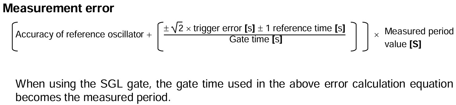
• The reference oscillator accuracy is the temperature characteristic of the reference oscillator.
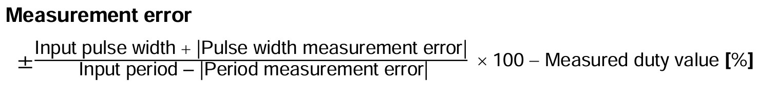
Duty ratio A(DUTY-A)
■ Measurement range and resolution |
||
|---|---|---|
| Input signal frequency range | Same as FREQ-A | |
| Measurement range | SGL gate | 0.01µ~99.999,999,99[%] |
| Internal gate | 2µ~99.999,998[%] | |
| Measurement resolution (Internal gate average count) |
SGL gate | 100ns/input cycle × 100[%] |
| 1~24 24~2,499 2,500~249,999 250,000~24,999,999 25,000,000 or more |
100ns/average input cycle × 100[%] 10ns/average input cycle × 100[%] 1ns/average input cycle × 100[%] 100ps/average input cycle × 100[%] 10ps/average input cycle × 100[%] |
|
Pulse width A(P.W-A)
■ Minimum pulse width |
6ns | |
|---|---|---|
■ Maximum repetition frequency |
80MHz | |
■ Measurement range and resolution |
||
| Reference time | 100ns | |
| Measurement range | SGL gate | 100ns~1,717s |
| Internal (1 ms to 10s) gate | 100ns to approx. 1/2 gate time | |
| Measurement resolution (Internal gate average count) |
SGL gate | 100ns~1ms |
|
1~24 24~2,499 2,500~249,999 250,000~24,999,999 25,000,000 or more |
100ns 10ns 1ns 100ps 10ps |
|
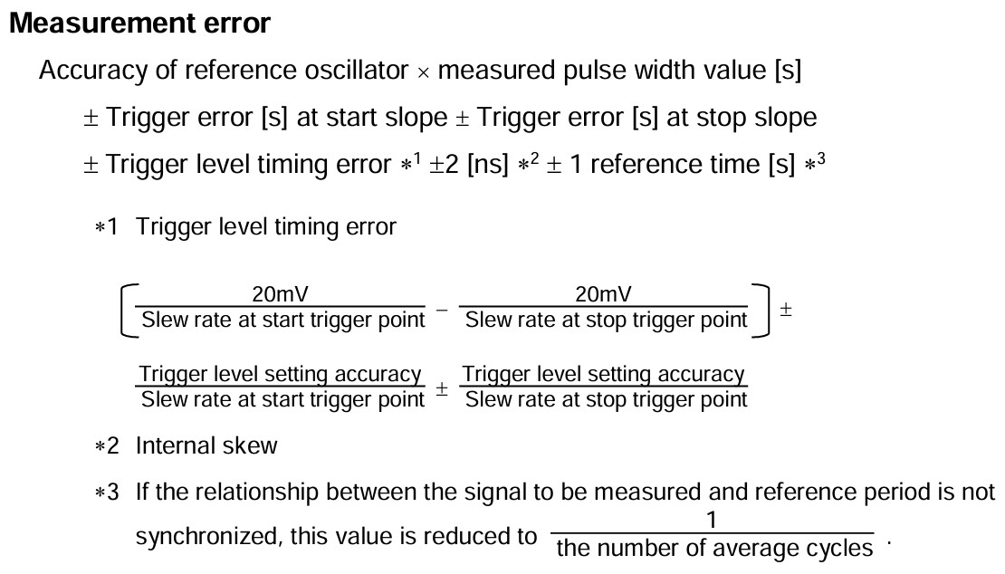
• The reference oscillator accuracy is the temperature characteristic of the reference oscillator.
Time intervalA→B (T.INT A→B)
■ Minimum time interval |
6ns | |
|---|---|---|
■ Maximum repetition frequency |
80MHz | |
■ Measurement range and resolution |
||
| Reference time | 100ns | |
| Measurement range | SGL gate | 100ns~109,951s |
| Internal (1 ms to 10s) gate | 100ns to approx. 1/2 gate time | |
| Measurement resolution (Internal gate average count) |
SGL gate | 100ns~100µs |
|
1~24 24~2,499 2,500~249,999 250,000~24,999,999 25,000,000 or more |
100ns 10ns 1ns 100ps 10ps |
|
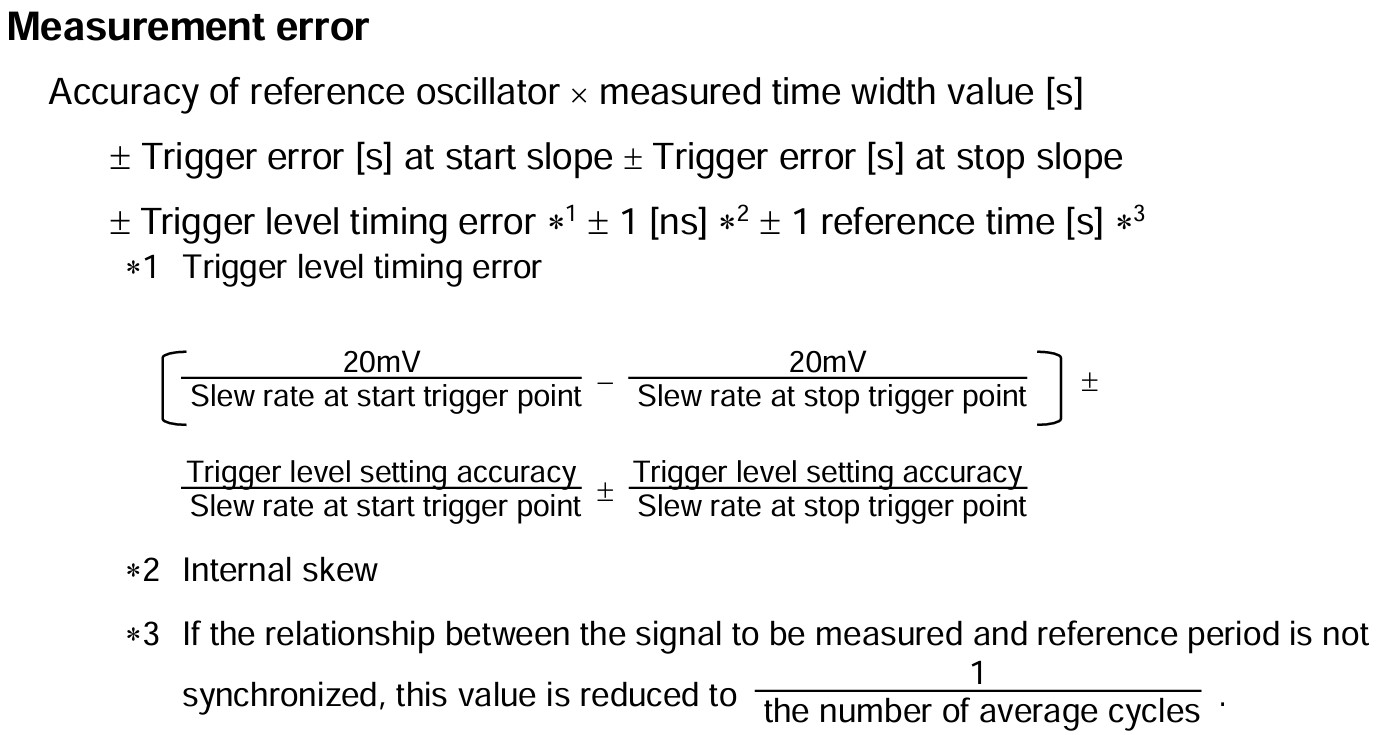
• The reference oscillator accuracy is the temperature characteristic of the reference oscillator.
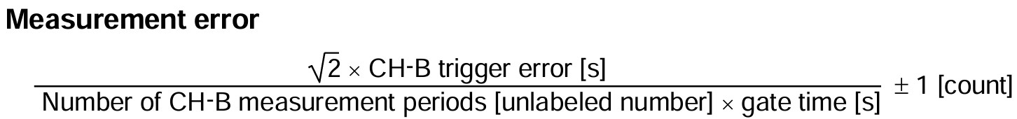
Frequency ratio A/B (FREQ A/B)
■ Measurement range and resolution |
|||
|---|---|---|---|
| Input signal frequency range | Both CH-A and CH-B are the same as FREQ-A | ||
| Measurement range | Internal gate(1ms~10s) | 1E-9~1E+9 | |
| Measurement resolution | Internal gate(1ms~10s) | 1 + LOG (CH-A input frequency x gate time) digits | |
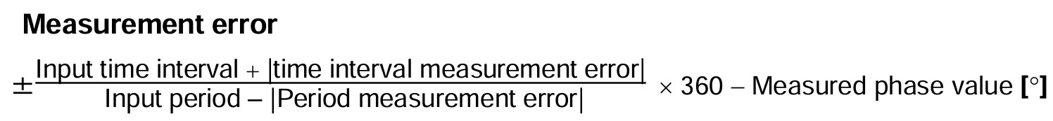
Phase measurementA→B (PHAS A→B)
■ Minimum time interval |
6ns | |
|---|---|---|
■ Maximum repetition frequency |
80MHz | |
■ Measurement range and resolution |
||
| Reference time | 100ns | |
| Measurement range | SGL gate | 0.1µs~359.999,999,9[º] |
| Internal gate | 10µ~359.999,99[º] | |
| Measurement resolution (Internal gate average count) |
SGL gate | 100ns/input cycle × 360[º] |
|
1~24 24~2,499 2,500~249,999 250,000~24,999,999 25,000,000 or more |
100ns/input cycle × 360[º] 10ns/input cycle × 360[º] 1ns/input cycle × 360[º] 100ps/input cycle × 360[º] 10ps/input cycle × 360[º] |
|
Addition counting measurement(TOT-A)
■ Minimum response pulse width |
2.5ns | |
|---|---|---|
■ Input frequency range |
Same as FREQ-A | |
■ Measurement range |
Counts from 0 to 4,294,967,295 when the scaling operation is OFF | |
■ Measurement error |
±1 [count] (only when the gate is opened and closed) | |
Peak voltage measurement
| The voltage amplitude of the CH-A or CH-B measured signal is measured and displayed in real time. | |||
■ Measurement frequency |
150Hz ≤ Input frequency ≤ 50MHz | ||
|---|---|---|---|
■ Measurement speed |
2 seconds or less | ||
| Measurement range | ATT OFF | -2.50V to +2.50V (10mV resolution) | |
| ATT ON | -50.0V to +50.0V (100mV resolution) | ||
| Measurement error | ATT OFF | 10% ±50mV of displayed value (for sine waves) | |
| ATT ON | No specification | ||
CH-A/B input terminal
■ Maximum input voltage |
200V(DC+ACpeak) | ■ Impedance |
Approx. 1MΩ//20pF or less |
|---|---|---|---|
■ Coupling |
AC or DC | ||
■ Low pass filter |
None or 10kHz | ||
■ Attenuator |
None or 26dB (1/20) | ||
■ Trigger level |
|||
| Measurement range | ATT OFF | -2.50V to +2.50V (10mV resolution) | |
| ATT ON | -50.0V to +50.0V (100mV resolution) | ||
| Measurement accuracy(0~+40ºC) | ATT OFF | 10% ±30mV of the set value (however, +2 to -2V is ±3%) | |
| ATT ON | 10% ±300mV of the set value (however, +40 to -40V is ±3%) | ||
■ Operating range |
ATT OFF | -2.50V~+2.50Vpeak | |
| ATT ON | -50.0V~+50.0Vpeak | ||
■ Input sensitivity |
|||
| Manual trigger | ATT OFF | 30mVrms(DC~230MHz) | |
| ATT ON | 0.6Vrms(DC~230MHz) | ||
| Auto trigger | ATT OFF | 200mVrms (10kHz to 230MHz for sine waves) | |
| ATT ON | 4mVrms (10kHz to 230MHz for sine waves) | ||
10MHz STD IN
| BNC terminal for inputting more stable reference frequencies from the outside. | ||
| Input frequency | 10MHz±50Hz(±5ppm) | |
| Input amplitude | 1Vrms~5Vrms Threshold = 0V | |
| Input resistance | Approx. 6.4kΩ | |
| Input coupling | AC | |
10MHz STD OUT /(MARKER OUT)
| BNC terminal for outputting internal reference oscillator or marker signals. A marker signal is a signal assuming the luminance modulation (Z axis) of the analog oscilloscope. It is valid when the function is the SGL gate of the time interval (T.INT A→B) and phase (PHAS A→B), and the period from the start of the CH-A measurement to the start of the CH-B measurement is output = L. |
||
| Output | CMOS level | |
| Reference frequency output | The 10MHz stability is the same as the standard transmitter on the main unit | |
| Marker output | Bandwidth 5MHz Output L for the actual measurement period. | |
Output interface
| RS-232 | Standard equipment | |
| GPIB | Factory option(SC-701) | |
| Digital I/O | Factory option(SC-702) | |
Environmental conditions
- Preheating time:At least 60 minutes
- Operating temperature/humidity 0ºC to +40ºC/85% R.H or less (no condensation)
- Storage temperature/humidity -20ºC to +60ºC/90% R.H or less (no condensation)
Reference oscillator
Equipped as standard. Can be output to the 10MHz OUT BNC terminal on the rear of the main unit.
- Oscillation frequency 10MHz
- Temperature characteristics ±2.5ppm/equipment ambient temperature 0ºC~+40ºC
- Change over time ±1.0ppm/year
Change in power supply conditions and power supply voltage (factory option)
- Power supply voltage 100VAC ±10% Change in power supply voltage (factory option):110~120V or 220~240V
- Power supply frequency 50Hz, 60Hz, 400Hz
- Power consumption 31VA MAX (at 100VAC with optional SC-701 and SC-702)
Size, mass
- Size:Approx. 210W × 99H × 353L mm (excluding options and protruding parts)
- Mass:4.0kg or less (when equipped with optional SC-701, SC-702, SC-703A)
Accessories
- Power cord (1), Instruction manual (CD-ROM) (1), User's Guide (1)
